Wednesday, September 29, 2010

CarBEN EV5 Open Source Project Part 3 - Updated 12 Jan 2011

CarBEN EV5 Part 1

CarBEN EV5 Part 2

CarBEN EV5 Part 4


The single entry is probably the most controversial feature of the CarBEN EV -- it has to do with weight savings and surrounding safety structure.

It's not like the the benefits aren't well worth the minor sacrifice: the CarBEN EV could well be the most efficient car yet made, and it could be one of the first electric cars to have a range of 400 miles (or more) on a single charge.  If I was able to take part in the X-Prize, the CarBEN EV would have held the most people of any car in the contest.  It might have a Cd under 0.14 and weigh less than a ton; hopefully less than a ton with the driver onboard.

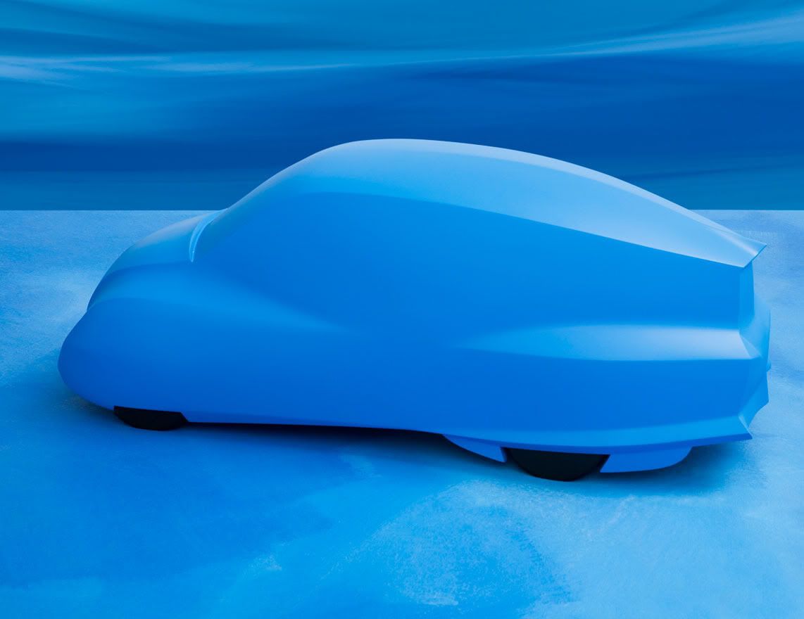
I'm serious about these goals, and I have to make choices that save weight, while not diminishing safety, and yes, body gaps add aerodynamic drag.  The Bionic increased the Cd from 0.095 (the early blue clay model that I am starting with) up to 0.19.  The main reasons for much of this increase is the uncovered wheels and the cooling for the diesel engine.

Since about 97% of all accidents involve impacts on the front and sides of the car, I want to have maximum protection in those areas.

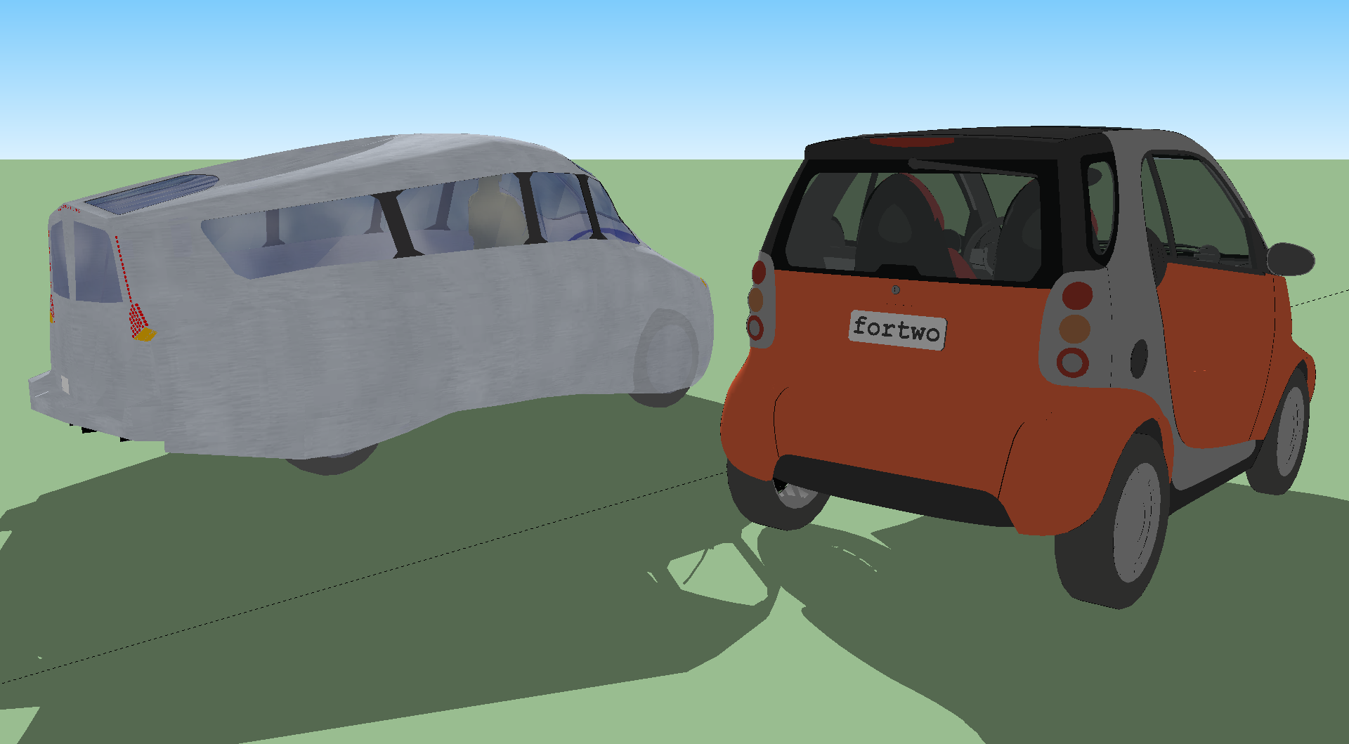
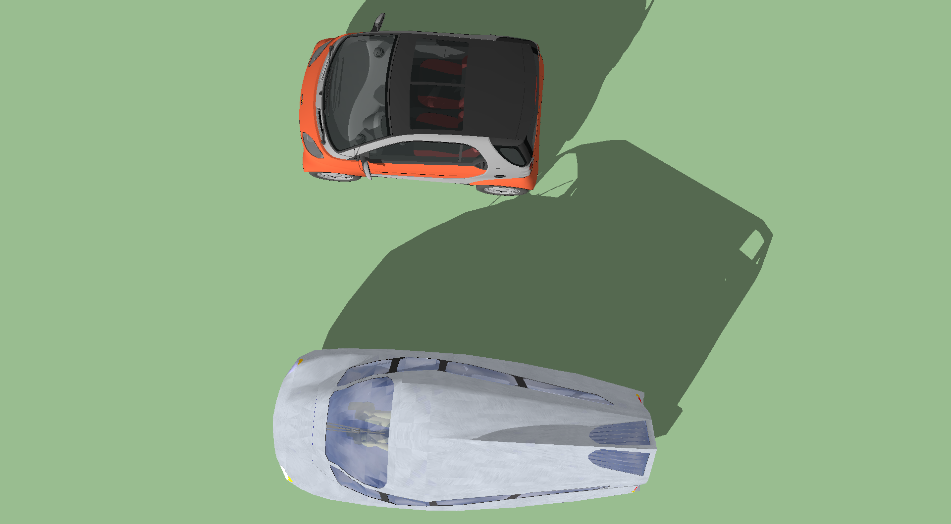
Since a square encloses the most area with the least perimeter (except for a circle, naturally), it is the best shape to make a car with a given frontal area, and it gets the most usable interior volume.  The Mercedes Bionic/Boxfish model provides an amazing opportunity: it combines an amazingly low coefficient of drag (Cd) in a shape that is nearly a square in the frontal area.  This makes it possible to have comfortable seating for 5 people in a car less than 14 feet long.

A compact car can be much lighter and stronger, and still keep the frontal area down to ~25 sq ft (2.323 sq m).  If the Cd of CarBEN EV is 0.14, then the effective frontal area (CdA) is 3.5 sq ft (0.325 sq m).  And it is possible to get the Cd as low as 0.11 or so, and that would lower the CdA to 2.75 sq ft (0.255 sq m).

These would be unprecedented drag numbers for any car, let alone one that seats up to 5 people.  Having an electric drive train also contributes a lot to this packaging efficiency: the electric motor is much smaller than an equivalent ICE and it's transmission (an electric motor only needs a reduction gear -- or can be direct drive!) and they need just a fraction of the cooling air flow.

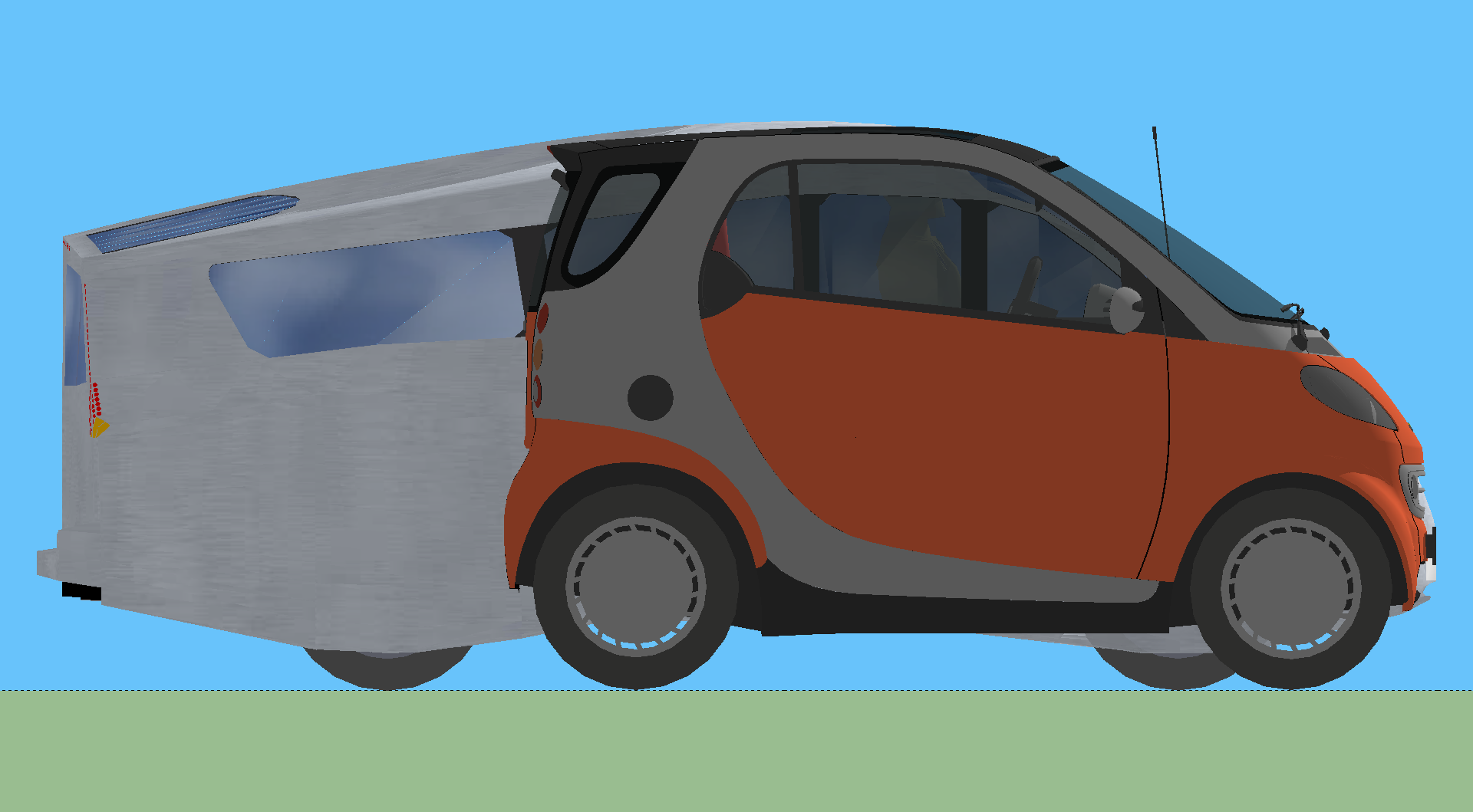
And here's one of the reasons where the aero and the aero shape enter into why the entry door is in the back: since truncating the back of the shape (called a Kamm back) makes the vehicle makes it much more practical, and has a very small increase in drag (and the Boxfish model achieves it's staggering Cd of 0.095 with a Kamm back), and this is where a small fraction of the accidents occur anyway, this is where I chose to put the main entry door.

Side doors add weight and reduce the safety; by cutting big holes in the structure (think about a large box beam web) which then has to be reinforced all around the perimeter, and the door itself has to have a similar frame all around the perimeter, and you add the hinges and if you want to have as much strength as possible, you need 2-4 latches (instead of the usual 1).  Adding the latches, means that you gain back some/much of the strength you had with no side doors, but it will weight more.

Since I would need a rear hatch door anyway if I put in a side door; I can save a lot of weight and get the safety protection even better than most cars.

Another aspect of the aero that affects many other things, including the seating arrangement: the tapered shape required for ultra low drag means that conventional rows of seats is not the best way to fit everything in.  Since the electric motor is so compact, the driver can be moved forward between the front wheels, opening up more room.  And the staggered seating means that even more legroom is available by angling your legs off to the side.  So, the CarBEN EV fits 5 comfortably, in a package that most cars fit 4 less comfortably.  The mesh seats are also a big part of this.

On the asymmetrical seating -- basically, the most the weight would be unbalanced is about 300-350 pounds (the two "extra" seats are for shorter adult/kids), and that weight is on the higher part of the road crown; and away from the much rougher right side edge. I've only ever had to replace wheel bearings and the like on the right side of any of my cars. The battery pack in the floor is 800-900 pounds, and since most cars have the driver on the left -- and most often the driver is the only person in the car; so, most of the time the CarBEN will be in total balance! On the other hand, most cars are usually out of balance by up to 250 pounds (or more).

I think I've shown that the choices I've made so far, are aimed at achieving unprecedented ultra-efficiency, in a compact, very practical people moving machine.  Since the most import part of that function is just that: moving people with safety, the small inconveniences of slightly more effort getting in and out of the car are more than offset, if I can get anywhere near the performance I think are possible.  Form follows function, and I think the CarBEN EV can function at a very high level, indeed.

As Oliver Kuttner says: you must get the physics right to get to higher efficiency; and all design choices affect the efficiency. Using less energy is my focus, and that is where I cannot compromise.

After I get a prototype and running, I hope to experiment with rigid wheels and solid (non-inflatable) tires and regenerative shock absorbers.  The solid tires and rigid wheels could be much lighter weight (which counts double to weight losses anywhere else), and they could have vanishingly low rolling resistance, and they would pass along most of the energy to the regenerative shocks; making their effect greater than it would be with conventional tires.

The ride quality could actually be better than with conventional tires, since light wheels makes the system more compliant (they move rather than moving the car), and the suspension can be fully tuned and damped to match the wheels.

This could help get the energy consumption even lower than 100Wh/mile, and that could extend the range, as well as recharging the batteries (a bit) from the energy regained from the shock absorbers (instead of wasting it as heat).  Every little bit counts.


****************

Here's the latest video animation: Final Design Intent Video

Here are the newest images and of the SketchUp model.  If you want a copy of the model, I'd be happy to email you a copy!


Some pictures of a 1/12th scale (1" = 1') model of the eggcrate frame similar to what could be used to lay the fiberglass shell:


Creative Commons License
CarBEN EV5 by Neil Blanchard is licensed under a Creative Commons Attribution-ShareAlike 3.0 Unported License.

Sunday, September 5, 2010

Oil Is Finite, Electricity Is Infinite

Oil has a lot of embedded energy to account for:

Exploration is getting harder all the time; and can take years; and lots of energy is consumed doing so.

Drilling is very hard to do, and takes a lot of energy, including making a lot of "drilling mud", which takes a lot of energy to make, and to inject deep down underground. Look it up! The BP drilling rig is nowhere the deepest at ~23,000 feet below the surface of the ocean.

Extraction takes a lot of electricity (with all of it's overhead!) -- possibly more than refining(!); never mind the energy to build and move and operate those gigantic oil rigs.

Transportation to land is expensive, and super tankers burn a lot of fuel, with it's overhead of embedded energy. The routes taken now have to be lengthened to avoid pirates, and pipelines are hard to build and maintain.

Oil then has to be pumped into tanks onshore for storage, and/or into pipelines. Any energy used along the way has it's own overhead of embedded power.

It then has to be transported to refineries; burning more fuel with it's embedded overhead.

Refineries use a lot of electricity (and all it's overhead!) and they use a lot of natural gas to heat the oil, in a process that takes days. There is a lot of blending and other chemicals used, all of which that have to be made ahead of time, using yet more energy and all of it's overhead. The various fuels and by products are then pumped again to storage tanks.

Then the gasoline/diesel is pumped and transported using pipelines, trucks, and trains, burning more fuel and using electricity, added yet more to the overhead.

It then has to be pumped into the storage tanks at the filling stations, and then pumped out again into the cars, using more electricity, adding that overhead of energy.

By rights, we should also include the military used to defend and maintain our access to oil, and maintaining stability in oil prices. There are huge hidden subsidies in foreign policy, too. Don't fool yourself to think that much of our battle with terrorism is tied to this whole messy and corrupt situation. Do you know how much oil gets stolen in the Congo or in Iraq?

I almost forgot -- it isn't just the fuel! ICE engines require a lot of lubrication and maintenance: you have to add in all the steps to find, produce, transport, store, refine, store, transport, use, then dispose of the engine oils used in the ICE. So, many of the same steps I listed above have to be repeated for the other consumable carbon based things used by ICE machines, including the lubrication oils and the filters, etc. This accumulates even more carbon footprint.

I HAVE PROBABLY OVER SIMPLIFIED THIS LONG AND ENERGY INTENSIVE PROCESS.

Electricity from coal, on the other hand is fairly easy: mining takes a lot of effort and energy, then moving it around in the storage yards, then transporting it on trains (which are the most efficient way to move anything!), then moving it around storage yards, then burning it, and disposing of the ash waste.  This fly ash can be used as aggregate in concrete.  Dealing with fly ash is a significant challenge.

Electricity generated from natural gas is more similar to making gasoline/diesel, except for the refining stage.  Coal produces the most carbon waste, but has less embedded energy, while natural gas produces far less carbon, but represents a greater amount of embedded energy; just not nearly as much as oil.

Grids losses are not as bad as you might think: the average is a bit less than 8% loss on the grid. Any and all of the overhead for electricity that is used at all the various stages along the way to produce oil -- get added to the oil! So, the 7.5kWh PER GALLON of gasoline could instead just be used directly to move a car 30-60 miles *rather* that making the gasoline.

Electricity can come from renewable sources: solar PV, solar heat, wind power, geothermal (by drilling deep holes!), biomass (methane from plant and animal waste and others), wave power, tidal power, small scale hydro, etc. The more we use of these, the smaller the carbon footprint becomes in the future, as we make the new wind turbines from renewable energy, and so on, and so on.

All of these use energy from our sun, in one form or another -- much more directly that oil an gas.  The Sun is our big-fusion-reactor-in-the-sky!

Each gallon of petroleum fuel represents ~100 TONS of biological material, that is millions and millions of years old. We are squandering it -- using so little of it potential. We should use it only when absolutely necessary.

The cost of electricity is very low compared to gasoline -- an EV can be driven the same distance as an ICE powered car for a fraction of the cost. And again, we are not talking price; but rather the amount of embedded energy.

So, in total gasoline/diesel represents a FAR GREATER amount of carbon per mile traveled -- even now before we produce very much electricity from renewable energy.

And that, my friends, is electricity's greatest strength -- it can come from a great variety of energy resources; many of them being renewable.

Petroleum in finite.

Electricity is (for all intents and purposes, until our Sun burns out) infinite. If we used mostly/all renewable energy sources, then we would not even have to conserve...

We *must* think very long term, if we are to survive on this Eaarth we share. We can live without a lot, but we cannot live without the Eaarth.

Friday, September 3, 2010

Eaarth

Originally posted on 14 Aug 2010:


"Eaarth" by Bill McKibben
"Read it, please. Straight through to the end. Whatever else you were planning to do next, nothing could be more important." —Barbara Kingsolver

I agree.

Please read "Eaarth".  Check it out from your local library, or buy it and pass it along to someone.

[From now on, I will be spelling the name of the planet we all share "E-a-a-r-t-h".]

More Vehicle Efficiencies!

This post is a continuation/generalization/more organized version of my earlier blog post.

There are a lot of improvements possible for internal combustion engines (aka ICE's).  It helps to list the areas that are causing losses, to start:

-- The geometry of the physical layout of the piston, connecting rod and the crankshaft is less than ideal.  The connecting rod needs to be ~60 degrees past top dead center to get the best leverage on the crankpin; but the pressure from the fuel ignition occurs much earlier than this; when the connecting rod is essentially trying to bend the crankshaft sideways.  The motion of the piston is necessarily sinusoidal.

- The power stroke is only 25% of the full cycle, and there is a lot of mass that has to be accelerated, stopped and accelerated again.

- The valvetrain has to physically resist being moved, and it has to work against the air flows.

- The piston tends to scrape the sides of the cylinder, because it would "rather" twist that stay straight.  The rings must exert friction on the cylinder.

- The oil must be pumped through little tiny passageways.

- Electricity must be generated.

- An ICE is a self-powered air pump, in essence.  Air flow and the pressures generated, and the cyclical nature of them cause resonances, and backpressures, and the gasses become spring-like.

- Small volumes, like the space above the top ring and the top edge of the piston, trap unburned fuel because the flame cannot reach it.

- Everything flexes and springs -- the crankshaft and the camshaft flex torsionally and longitudinally, the piston vibrates and distorts, as do the cylinders.  Valves bounce and stretch and distort into potato chip shapes.

The list goes on...  The net result is a typical internal combustion engine that uses ~20% of the energy in the fuel for output motion at best, and requires a transmission to keep the torque of the engine relatively close to the speed of the vehicle.

So, knowing all this, how can we make incremental or wholesale improvements?

+ Offsetting the crankshaft center away from the power downstroke gives the connecting rod some better mechanical leverage -- but is the compression stroke adversely affected?

+ Variable valve timing allows the torque to be available over a broader range of RPM's.

+ Valves can be electrically/hydraulically moved in both directions (opened and closed) to avoid fighting the springs.  This also makes it easier to use subtle or more abrupt adjustments to the valve timing.

+ Use cams rather than the crankshaft, to gain a lot more mechanical leverage, and to allow the piston motion to be controlled by the designer; like the Revetec:

This particular design also reduces piston scrape (but it introduces some tendency to spin the piston within the cylinder).  It also avoid big changes in crankcase pressures (in configurations with even numbers of pistons).  This design effectively doubles the efficiency.

+ Use the Atkinson valve timing, like the Prius does, which has a lot of overlap of the exhaust valve with the beginning of the intake downstroke (I think?) so that there is built in exhaust gas recirculation (aka EGR).  This also effectively doubles the efficiency.
Hmmm, how well would a 2-cylinder Revetec with Atkinson cycle and electrically activated valves work?

+ Use a rotary design that reduces the reciprocal motion.

+ Use a 2-stroke design to cut the parasitic losses in half.

++ Use a continuous burn design to further reduce the cyclical nature of the engine; or at least reduce the time between power cycles.

+ Figure out how to reduce waste heat from being produced, and then try to use the remaining excess heat to produce output.

What are other ideas to improve ICE's?

X-Prize Knockout Round - Con't.

Originally posted 1 July 2010:

Progressive Automotive X-Prize Knockout Round!

Originally posted on 22 June 2010:


I am at the Michigan Speedway, as a volunteer member of the Edison2 team -- Oliver Kuttner made this generous offer and I was all too happy to accept. I have a fair number of pictures, which I am starting to upload. I arrived Sunday (which I calling Day 1, even though it was just setting up; and I'll be here through Friday! :-)

We have been very busy so far, prep and cleaning up loose ends -- two of the four Edison2 cars go in for technical inspection Monday the 21st, and two go in Tuesday the 22nd. The first Edison2 Very Light Car tandem (#95 which was the one without wheel pods at the Shakedown) passed this morning and the first of the two mainstream cars was in the process. The weight of the #95 car was 702 pounds. I not sure how this is figured, but it will be required to carry 99 pounds of ballast weight.

I saw the Aptera for my first time in person, it looks very good "in real life". And I got to sit in the driver's seat -- there is almost too much leg room, and I fit well, though there is not a lot of "extra" head room. (I'm 6'-4"). For that matter -- obviously, this is the first time I have seen any of the vehicles: the Illuminati Seven, the FVT eVaro, the Twike, the X-Tracers, etc., etc. Pretty cool stuff all of it!

The cars that had not completed all the tests in the Shakedown were here earlier last week and they are taking runs on the (very large, high banked) oval track. Other events will happen on the road track.
Tomorrow (Tuesday the 22nd) will be more tech inspections, and the "biggie" economy runs that are the raison d'être are on Wednesday and Thursday! And actually there will also be economy runs on Friday, which is the Public Day, but that schedule has not been fully settled yet.


CarBEN Concept EV: An Open Source Project


  CarBŒN Concept EV

An Open Source Project
Revised 17 September 2010

I've been revising the model in SketchUp (and I can email you the file if you want!), and here are some new images:
 
Slightly older version:
 

Some images comparing CarBŒN v Smart ForTwo:


Some of these were rendered for me by C. Michael Lewis, from Portland ME. Proving it is a small world, he works both in architecture (and has mutual friends) and he races in the Electrathon series, and he currently holds the speed record of 62 Miles in an hour; while getting 2,249MPGe!

This is the first model, made from basswood:

 
Project Outline

Design and build an uber-efficient electric car; that has very low aerodynamic drag, as low weight as possible, is designed with good safety and crash protection, is practical to drive (i.e. it is not too big and has nimble handling), and I would like it to carry 4-5 people. By the way, the reason I chose the name
CarBŒN: it is a play on the word carbon (I want to not waste any), and the change in spelling are my initials backwards; combined with the correct spelling... :-)

The basis for the aerodynamics is an early clay model of the Mercedes Bionic car (aka “Boxfish”) that was itself based on the boxfish. The tested coefficient of drag (Cd) of this model was an amazing 0.095 (http://www.ae-plus.com/key%20topics/cc-mercedes-news10.htm) and it seems like a great place to start! The later Bionic car had a Cd of 0.19, which is still very good; but the open wheels and wider shape in the back are the primary reasons for the increase in drag. Another design that inspired a lot of the CarBŒN design is the Schlörwagen – a very aerodynamic design from 1939.

My idea that will allow the wheels to remain covered, and therefore (hopefully) achieve a Cd nearer to the blue model than to the Bionic car, is to have articulated front wheel covers that move with the wheels in sharper turns. I'll get more into the details of how this could work later on.

To achieve low weight, I think the ideal structure would be carbon fiber reinforced plastic. But this is difficult for me to work with, as I have no experience with it, and I think the prospect of making molds and the fumes, etc. is daunting. I've also considered welding a steel tube chassis, and then make either a fiberglass or aluminum body. But I think this would be heavier, and while I have access to a MIG welder; it is not as good as an aluminum monocoque chassis.

I got the idea for how to do this from seeing a friend who is building an airplane from scratch. It is a 2 seat acrobatic capable, and the dry weight (including the 4 cylinder 80HP engine) is between 570 and 620 pounds. I think the process he is using, which plotting out full size templates, and then forming the 6061-T6 sheets into the ribs and the skin; using wooden forms – makes a lot of sense to use this method to build this car.

Aluminum is fully recyclable, it is not dusty, has no fumes, and only requires a small bandsaw, a pair of “pleating” pliers, a soft hammer, and riveting tools. If I start with a 3D CAD model and drawings generated from that, the templates will be accurate. The resulting chassis should be lighter than I could manage with steel, and it forms the body at the same time.

Starting with the Sonex airplane (http://www.sonexaircraft.com/aircraft/sonex.html) and its weight of 620 pounds (~130 pounds for the engine is included in that) – the 22' wingspan and 18' long fuselage have roughly similar surface area to my CarBEN design and so it should weigh about the same (490 pounds). The AC electric motor and mechanical drive train are maybe a little heavier than the plane's engine; say 150 pounds. Add the four wheels, brakes, and the suspension (say 250 pounds) and the battery pack (say 400 – 600 pounds), the seats (which will be quite light – more later) and miscellaneous stuff will add 150 pounds. The the total vehicle weight could be in the 1450-1650 pound range. I would be very happy with anything under 1800 pounds.

The first order of business is to get the overall chassis to be as low drag as possible: I can loft a 3D CAD model from the wooden model I have made, but I think it would be better/faster/cheaper to have the model 3D scanned and use the mesh model for virtual aerodynamic testing. A program that can do 3D flow would be very important to check the form and to adjust it to lower the drag as much as possible without making it impractical to drive. i.e. I'm 6'-4” and I want to fit comfortably, and I need to fit my family, too.

For the safety considerations, the first thing I am doing is making the structure surround the passengers, and in order not to weaken it with doors, like most cars do. Like all design decisions, this involves some compromise, and I have been considering what some other designers have done: both the VW 1L and the FVT eVaro have canopies (like a jet fighter airplane), so that the structure around the passengers is continuous; the compromise comes in inclement weather, as the roof is not over the seats. Another car design that uses an unusual door and entry method is the Loremo; the entire windshield and hood hinge up (from the front) and you step over the side and pull the door back down in place. This also involves the steering wheel and column hinging up and out of the way with the door. The passengers get in through the rear hatch (and they sit facing backwards).

So, the initial door concept I am hoping to use is: in order to maintain a wraparound structure for safety, there is a single door in the rear of the CarBŒN. It has two parts: a sloped hatch that is approximately the back 1/3 of the roof; it lifts up but remains (mostly) covering the opening from precipitation. The rear fascia of the car is a pair of small hinged doors that swing out. This is a a good a place as any to put in the drawing:

CarBŒN Concept EV Mk 2.7
(I need to update the drawings to reflect the latest computer model.)

To get in the CarBŒN, people would step up to the floor, and then turn to close the back doors, and the walk up the “aisle” to their seat. (This hopefully explains the staggered seat placement?) The overhead hatch would be closed – the details need to be worked out. If this door idea is not workable, or involves too much effort, then the fallback solution is to have conventional side doors – but I would use 3 or more latches (instead of the usual one) so that the door has 5 (or more) points of attachment (instead of the usual 3) so that the opening is not unduly weakened, and the passengers would be well protected from side impacts.

The other key solution to getting the CarBŒN to work within a very low drag chassis, is the idea of articulated front wheel skirts (see the top, side and bottom views in the drawing).  [Edit: I think these would be easier to make, using a vertical hinge down the center (or steering pivot) line, with a front section and rear section.  Only the section that is needed to protrude out to allow room for the wheel would be moved.  This system would be much simpler than the first idea I came up with, which follows.]: These consist of a ¾ moon panel on the bottom (shown with a dotted line) and another ¾ moon panel on the outside of the front wheel (also shown with a dotted line). There is a slot in the bottom panel where the wheel protrudes out, and there is an inner fender and curved panels that keep the wheel covered even when the steering is all the way to one lock or the other. The suspension motion of the wheel does not move the skirt assembly – the tire moves up and down through the slot and within the inner fender. The whole assembly pivots on grooved rollers around the edge of the bottom panel (see the small circles on the bottom view drawing) and a pivot at the top of the inner fender.

The steering pushrods are connected to the skirt assembly, and swing it with the wheel when the steering angle is sharper than needed for highway driving. So, at high speeds the aerodynamic shape remains unchanged, but at low(er) speeds when sharper steering angles are needed, the panels move to maintain clearance around the wheels. This is the biggest compromise made in the Schlörwagen design – they made the front wide enough to enclose the wheels even when they are at either steering lock. The Schlörwagen is 2.1 meters wide (6'-11”) which has a large affect on the area and hence the drag (CdA) and the car is wide; making it more difficult to drive. It also means there would be more body roll than would otherwise happen.

The battery pack (the 4' x 4' x 6”rectangle) should fit in the floor, between the four wheels. The AC electric drive train is a typical front wheel drive system; which will provide the best ability to have regenerative braking, to regain some of the power. I intend to use a super capacitor in parallel with the battery pack, which allows higher current to be absorbed from regenerative braking to be absorbed, and it can provide bursts of high current for acceleration, greatly reducing the battery load during charging and discharging, while driving. The folks at http://chargecar.org/ (at Carnegie Mellon) are working on enhancing this kind of system with “smart” programing that uses data from your commonly driven routes (using GPS to locate where you are driving) and elevation data to “anticipate” how to best manage the regenerated power, and to make the best use of the supercapacitor; as a power cache.

In order for me to design a simple braking system (without the complexity of an integrated braking system), I would use two brake pedals: the center pedal would be a conventional brake pedal, that operates the hydraulic braking system. This would let the driver's habits be the default in a panic situation. The pedal on the left (about where the clutch would be in a manual shift car) would be the regenerative brake pedal. This would allow for a true coasting mode – both feet off of all pedals, that is easy an predictable. (This is key to good ecodriving; no matter what is powering the car.) Then, if some slowing is needed, the driver can use the regenerative brake as much as possible, and then use the hydraulic brake to supplement the regenerative brakes, if needed.

To save weight and space inside the car, I would make the seats with a mesh fabric stretched over frames; like some office chairs. This sort of seat are now being used in several concept cars, from VW, Toyota, and Honda for example. With the right ergonomics, these would be very comfortable, even for long trips, and they would “breathe”to help keep people cooler in the summer; reducing the need for other cooling methods.

I will try to make an effective passive air circulation system, with the intake(s) located in high velocity areas on the front or sides of the car, and I would provide for passive air extraction out the back of the car; exhausting into the low pressure wake zone at the back of the car. This could actually improve the drag a little; or at least minimize the increase due to the air flowing through the car. This passive air flow could also be tapped to cool the battery pack, and or the electric motor if needed.

The wheels and tires initially would be conventional, but instead of inflating the tires with air, I would use a foam – this would negate the need to keep track of the pressure, and it would probably minimize the rolling resistance, and tire wear would probably improve, because the temperatures would be kept low, since there would be virtually no flexing. The suspension would be designed to do all of the work (air inflated tires absorb a fair bit of the smaller bumps in the road), and it would provide very low rolling resistance. Later, I would install regenerative shock absorbers (apparently, these are currently being developed at Tufts University), and as much of the energy from the motion of the suspension as could be regained would help reduce the losses, by recharging the battery pack a little. (Rather than being wasted as heat in the tires and in conventional hydraulic shock absorbers.)

My intention is to test the aerodynamic drag virtually, using a 3D “solid” model. The computer model could be made from the wooden model, using laser scanning, or it could be made from scratch based on the 2D drawings that I've made based on the wooden model.  If there is anybody who is interested in contributing work on this computer model, please contact me.


The standing figure is 5'-9" tall for a visual reference, and these are perspective images, so things closer to you appear larger.  The windows and lights are a first pass, so do not read too much into them, though I think that they are schematically close to what is needed.

My next step is to test the 3D model in a CFD (computational fluid dynamics) program to see if it is aerodynamic enough -- hopefully I can then make improvements in it, and start thinking more about the chassis construction.


I made a video animation of the model in SketchUp on YouTube: 


I will lay them out in DataCAD to try and fit as many as possible on each sheet.  I'd like to be able to test the physical size and layout of the entry method and seat layout etc., before committing to build this car.

Now, I want to have a composite foam sandwich monocoque, both for strength and for thermal insulation, so do I need to form the inner walls on the inside of the formers first, and then do the outer surface, and then foam in between?


How do I best form the surface using the formers?

Do I need to use Styrofoam and carve it, or can I use wires and/or screening as a substrate for the composite?
It is okay to leave the plywood in place and have it as part of the structure, or is is better to pull it out and then rejoin the surfaces with spacers/foam?
Is fiberglass significantly less expensive than carbon fiber, and what are the advantages/issues with each?

I can cut the plywood so that the windows are slightly recessed, to form the lip/flange -- should the windows just be left open and trim the edges, or does it help to cover them over completely and then cut out the openings?

For the main hatch door, and the rear doors, should they be formed as part of the whole outer skin, and then cut out?  Or, should the opening be left out of the main piece and then make the doors themselves separately?

I want to form a surrounding "beam" around the front and sides of the passenger compartment (which will double as the main air duct into the passenger compartment) -- I hope to have it flush on the inside, and let it into the formers.  If the beam was metal, it could be hollow -- can it be made from composite and be hollow?


I'm trying to figure out how to best do the crumple zone in the front: a tubular subframe or a composite structure?  Have you seen "crush cones" used between a structural bumper and the firewall/structural passenger cell?


How does the suspension get attached to the monocoque -- do reinforcing plates need to be embedded, or...?


I'm hoping to hear from FVT about the size of their battery pack, so I can try and lay out how it will fit inside the floor.  I would ideally try and at least have the space for a really big battery pack (50-60kWh!!) so I can get 300-400 mile range.  This would be incredible if it could be made to fit!


I would love to hear whatever your thoughts are!  Thanks in advance.


Creative Commons License
CarBEN EV5 by Neil Blanchard is licensed under a Creative Commons Attribution-ShareAlike 3.0 Unported License.